Star delta y d 3 phase motor starting method by automatic star delta starter with timer. A series wound dc motor like in the case of shunt wound dc motor or compound wound dc motor falls under the category of self excited dc motors and it gets its name from the fact that the field winding in this case is connected internally in series to the armature windingthus the field winding are exposed to the entire armature current unlike in the case of a shunt motor.
 Compound Motor Wiring Diagram Wiring Resources
 Same voltage is applied to both shunt winding and armature in this motor.

Compound dc motor wiring diagram. Motor connections your motor will be internally connected according to one of the diagrams shown below. Compound wound dc motor wiring diagram compound wound dc motor or dc compound motor electrical4u a compound wound dc motor or rather a dc wiring diagram for a compound wound dc. These interpoles have one winding of heavy wire and are connected in series with the armature as shown in figure 1.
Use figure 1 if your motor has a single voltage shunt field. The dc shunt wound motor running on direct current has its field windings placed in parallel to the armature. Wiring a dc motor and universal motor for speed control.
One of them causes the motor to completely loose speed control and the motor takes off. These connections are in accordance with nema mg 1 and american standards publication 06. There are three types of dc.
This parallel configuration allows independent path of current for field winding and armature. Electrical shunt diagram information about schematics pdf. We will go through all the possible loose connections for the shunt dc motor.
A compound wound dc motor also known as a dc compound motor is a type of self excited motor and is made up of both series the field coils s 1 s 2 and shunt field coils f 1 f 2 connected to the armature winding as shown in the figure below. Compound dc motor wiring diagram download read online. Three phase motor power control wiring diagrams three phase motor connection schematic power and control wiring installation diagrams.
I use a vacuum motor electric lawn mower and treadmill motors to demonstration some cheap options for speed control and wiring to the wall. Commutating field interpole of dc motors nearly all shunt and compound motors of 12 horsepower or more have commutating fields or interpoles located between the main poles. Download compound dc motor wiring diagram free files.
That is the reason behind naming it a dc shunt motor. Download compound dc motor wiring diagram pdf. This video is a lot more exciting.
Use figure 2 if your motor has a dual voltage shunt field. In electrical terms parallel is generally denoted as shunt. Electrical machines laboratory 2 lab manual pdf.
Motor wiring diagram dc. Motors characterized by the connections of field winding in they are shunt wound dc motor series wound dc motor compound.
 House Wiring Dc Go Wiring Diagram Motor Circuit Diagram Wiring Diagram Srv
 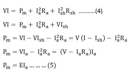 Types Of Dc Motor Shunt Series Compound Wound Motor
  Dc Motor Wikipedia
 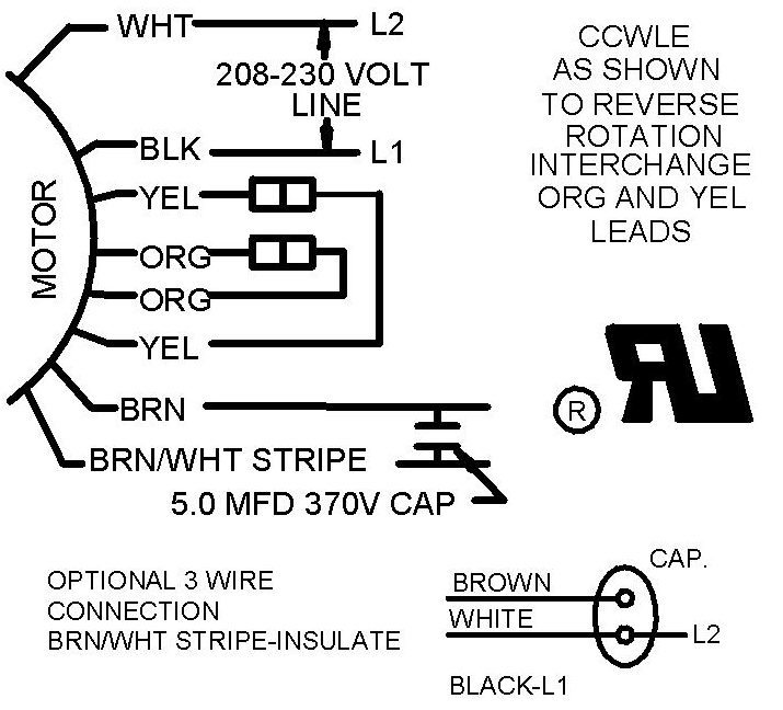 Motor Wire Diagram Wiring Diagram 500
 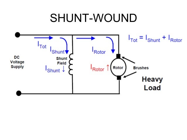 Chapter 2 Latest
  Dc Shunt Motor Speed Control Characteristics Electrical4u
  Use Of Dc Motors In Mines Operation Inspection And Maintenance
  Don T Ignore The Humble Brushed Dc Motor Mouser