Relative velocity between the rotating magnetic field and the rotor. 12 lead 3 phase generators may be connected for single phase application.
 Pdf Study And Measure The Active And Reactive Power
 Other fans as shown brown black blue m 1 greeny ellow brown cap black ce31 only single phase ac motor with capacitor blue or grey a n sildes these diagrams mainly apply to external rotor motorsbut some standard.

Induction generator wiring diagram. Click on connection diagrams for a link to the wiring diagrams for 3 phase and single phase generators. 100k ohm at room temperature. Start stop of induction motor with the help of magnetic starter on off three phase motor connection power control schematic wiring diagrams basic electrical wiring electrical circuit diagram electrical symbols electrical safety engineering technology electronic engineering electrical engineering circuit drawing power supply design.
1o wiring diagram diagram er4 1o wiring diagrams m 1 lne 3 active wires plus auto reset thermal contacts codes. Terminal markings and internal wiring diagrams single phase and polyphase motors meeting nema standards b. I use one of product avrto generator.
63 64 67 68 lf temp sensor too hot lr temp sensor. Replace applica ble generator circuit board left or right see wiring diagram. Verify the inductor temperature sensor is properly installed and not damaged measure approx.
Induction generators are also called as asynchronous generators. Generator is the name given to the class devices that convert. Before starting to explain how an induction asynchronous generator works i assume that you know the working principle of an induction motor.
Verify induction temperature sensor is properly connected see wiring diagram. The induction motor is powered from home 120v ac current im only using the motor because it much easier to. 3o wiring diagrams 1o wiring diagrams diagram er9 m 3 1 5 9 3 7 11 low speed high speed u1 v1 w1 w2 u2 v2 tk tk thermal overloads two speed stardelta motor switch m 3 0 10v 20v 415v ac 4 20ma outp uts diagram ic2 m 1 240v ac 0 10v outp ut diagram ic3 m 1 0 10v 4 20ma 240v ac outp uts these diagrams are current at the time of publication.
10 lead 3 phase generators are limited to high wye series star and low wye parallel star connections and cannot be connected for single phase application. In an induction motor the rotor rotates because of slip ie. But function via the same principle electromagnetic induction.
Find ac generator wiring diagram related suppliers manufacturers products and specifications on globalspec a trusted source of ac generator wiring diagram information. Alternator demo wiring connection to battery capacitors inverter modification. Capacitor start capacitor run induction motor.
This type of motor is designed to provide strong starting torque and strong running for applications such. Capacitor start capacitor run induction motors are single phase induction motors that have a capacitor in the start winding and in the run winding as shown in figure 12 and 13 wiring diagram. If a single phase motor is single voltage or if either winding is intended for only one voltage the terminal marking shall be determined as follows.
 Magnet Coil Power Supply By A Self Excited Induction
  Connection Diagram Of The Single Phase Induction Generator
  Figure 6 From Isolated 3 Phase Self Excited Induction 28 Single Line Diagram 3 Phase Star Delta Motor
 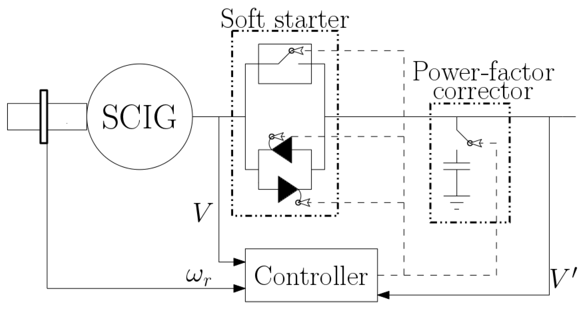 Energies Free Full Text A Review Of Wave To Wire Models
  No 13 Winding Diagram For An Ac Motor Jmag Simulation
  Wound Rotor Induction Generator With Variable Slip
  Generator Head Wiring Diagram
 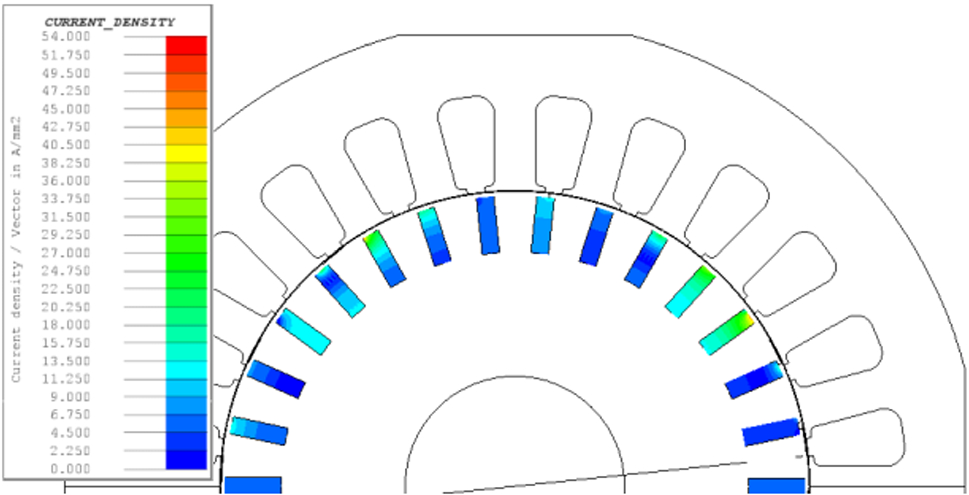 Comparative Analysis Of Single Phase Self Excited Induction